We are now at the PCB design phase of the first PCB for this product.
I have stripped the multi channel reference design of what we don't need and winded up with the attached schematic.
Can someone quickly check it over to see if I've cut anything vital out?
I basically want to know that it's going to work before we press on and I've not over cropped it or forgotten something.
Thanks!
Is this cut-down okay?
Is this cut-down okay?
- Attachments
-
- XMOS multi ch cut down.pdf
- (123.27 KiB) Downloaded 332 times
 XMOS multi ch cut down.pdf
- (123.27 KiB) Downloaded 332 times

Will you be using the USB interface for this project ? If yes, do not immediately see any ESD protection on the USB data lines (D+, D-) nor Vbus. That is a must for any USB design.
Please review some very low cost but practical solutions here:
http://www.xcore.com/forum/viewtopic.ph ... ilit=socay
Socay has parts for under $ 0.10 USD in single T&R (tape & reel) quantity that will be ideal. When you proceed to layout the PCB, you will need to impedance match the USB traces for best signal integrity. The same details should be relayed to the PCB shop to request if they can support impedance matching and supply supporting TDR reports to confirm this task has been completed for your actual project. We can supply some fair cost, low volume prototype PCB shops in Asia upon request that do support impedance matching. We have just completed a USB 3.1 to Gigabit design with success on 4L using the same PCB supplier.
Are you strict on the applied voltage regulators ? There are lower cost options you may wish to consider.
Hi thanks very much for the reply.
The USB lines are going off to an isolator as per the attached image. VBUS is not used as I thought this was only for XMOS = host. This device will only ever be slave to a PC. Powered internally by LDO, and external power goes to the isolators port facing side.
Matching will be done later yes.
We are currently happy with the chosen regulators. Although cost is a factor, the product itself is not a low-cost item so there's a bit more room. Same with production we are planning to produce this in the UK.
Final quotes will decide if that's possible but being made in England and using Western parts is a big factor for our business at least at the moment.
Analog is a good company but still recommending the inclusion of ESD protection devices. Socay parts references are very inexpensive and will allow for 15kv protection of your USB interface. The same footprints are available through other vendors.
For example:
Part Number: Socay ULC0524P
Quantity: 3 K
Unit Price: 0.042 USD/ pc
Same as Littlefuse SP3010 device:
http://www.littelfuse.com/~/media/elect ... et.pdf.pdf
Also recommend to include EMI filters onto the USB data lines. You have many options here to support filtering of USB 1.1 to USB 2.0 HS speeds.
One option is a single package device that offers EMI filter + ESD protection:
http://www.st.com/web/en/resource/techn ... 282307.pdf
We did not select the above ST device for our designs due to the single sourcing / single vendor of this component. Instead we selected a traditional EMI filter with multiple suppliers (Murata, etc. have the same footprint as our Kingcore / Inpaq supplier = SMD 0805 footprint)
http://www.inpaq.com.tw/Specification/M ... on_A23.pdf
http://www.digikey.com/product-detail/e ... -ND/765220
https://product.tdk.com/info/en/catalog ... 012_en.pdf
Offshore pricing is under $0.10 USD for this common mode choke device.
EMI filtering is often required to comply with FCC Class B emissions. For the very low costs of these parts + a bit more for component placement fees, well worth the investment for a more robust design. While there is a temptation to use an oddball ESD+EMI filter device in a single package, often the footprints are again unique, single sourced and that is a high risk to keep the same design in production for the future. Also, we have noticed that the ESD protection is minimal on such combo parts as compared to using a dedicated ESD protection component which is able to support assorted IEC levels of protection ( IEC61000-4-2 (ESD); IEC61000-4-4 (EFT); IEC61000-4-5 (Lightning) compliant).
Thanks again
So can I just be clear here, the Analog device we are using for data line isolation with >25kV/us does not effectively cover ESD?
Also are these devices included in the multi channel dev kit already? Have I cut them out of the schematic?
This device is battery powered so does not connect to the USB power line (unless it has been selected to charge via a physical switch), and the data lines are going through the Analog isolator. System will be running in in 12Mbps at all times.
Isolation and ESD protection are different topics. The isolation is to separate the ground potentials from one side of the interface to the other. This often recommended for long wires between connected equipment across industrial floors (ie. RS422 / RS485 interfaces, etc.). As there may be a risk of having a different ground potential between the connected nodes which is very dangerous.
For your project, most likely recommended to remove noise between the connected pieces. While the isolator features some ESD protection, we follow the recommendation from Bill Rusell of Semtech who stated that off die ESD protection is always preferred over on die protection. Specifically, should a surge event peak high enough to destroy the TVS diode, better to replace the external ESD device than this digital isolator which is a much higher cost component.
Speaking from very high volumes of deployment of industrial designs, the use of external ESD devices are worth the effort to place them into every design. The USB ESD devices recommended from Socay are under $ 0.10 USD each (alternate low volume parts are available with the same footprints from Digikey for < $ 1.00 USD each or less). One device can ESD protect your USB 2.0 lines as a first stage of protection.
Personally also recommend to place in line ESD EMI filters onto the same USB 2.0 lines (0805 footprint). Again, offshore suppliers are < $ 0.10 USD each for these EMI (common mode chokes) for USB 2.0 support but you can source many "brand name" of the same footprint from Digikey for $1.00 or less in single qty. Many of the offshore firms produce for the major brands - most of this industry is marketing.
Our design philosophy is to design once and never have the shipped product come back. For this reason, we often do throw in the 'kitchen sink' but can sleep at night knowing we put out a solid product that we would feel comfortable in buying. Not sure which makes of USB connectors you will use but that is another topic of discussion. Here, you want to work with a vendor that has solid experience and not the bottom dollar. We do recommend 30u" of gold plating as an exhaustive study was done by X-Multiple on the impact of assorted levels of gold plating on connectors and how it relates to the number of insertions / removal of the respective connector.
See here:
http://www.xmultiple.com/Mating%20Cycle ... Cycles.pdf
The last thing you / we want is to have a widget that you will pay a fair price for only to find that the connector must be inserted with special care while lifting your right leg and saying a prayer before it works correctly. For this reason, we buy only 30u" gold plated contacts on our USB connectors. Some vendors to consider are FCI, TE, Molex, etc. When selecting your USB connector, do recommend to use one with through hole board locks to properly secure the USB connector onto PCB. SMD versions that lack this through hole support could peel off the PCB and render the product useless due to failure of the approximately $1 connector.
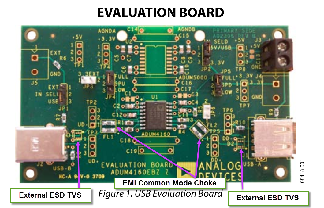
The ref design does not appear to feature any external ESD protection. In fact, neither does the Analog isolator ref PCB but Analog does recommend this as an user add-on component on the PCB layout.
See here:
http://www.analog.com/media/en/technica ... UG-043.pdf
* page 5 shows D2 for the external ESD protection device
* you have many options for such devices but we use Socay for our products (USB 2.0 & USB 3.1)
* for EMI filters we use Kingcore (Taiwan) but there are many other vendors who offer the same footprint (Taiyo Yuden, Murata, etc.). We selected 0805 footprint so we could prototype with local vendors while waiting for the offshore goods to arrive.
For your project, most likely recommended to remove noise between the connected pieces. While the isolator features some ESD protection, we follow the recommendation from Bill Rusell of Semtech who stated that off die ESD protection is always preferred over on die protection. Specifically, should a surge event peak high enough to destroy the TVS diode, better to replace the external ESD device than this digital isolator which is a much higher cost component.
Speaking from very high volumes of deployment of industrial designs, the use of external ESD devices are worth the effort to place them into every design. The USB ESD devices recommended from Socay are under $ 0.10 USD each (alternate low volume parts are available with the same footprints from Digikey for < $ 1.00 USD each or less). One device can ESD protect your USB 2.0 lines as a first stage of protection.
Personally also recommend to place in line ESD EMI filters onto the same USB 2.0 lines (0805 footprint). Again, offshore suppliers are < $ 0.10 USD each for these EMI (common mode chokes) for USB 2.0 support but you can source many "brand name" of the same footprint from Digikey for $1.00 or less in single qty. Many of the offshore firms produce for the major brands - most of this industry is marketing.
Our design philosophy is to design once and never have the shipped product come back. For this reason, we often do throw in the 'kitchen sink' but can sleep at night knowing we put out a solid product that we would feel comfortable in buying. Not sure which makes of USB connectors you will use but that is another topic of discussion. Here, you want to work with a vendor that has solid experience and not the bottom dollar. We do recommend 30u" of gold plating as an exhaustive study was done by X-Multiple on the impact of assorted levels of gold plating on connectors and how it relates to the number of insertions / removal of the respective connector.
See here:
http://www.xmultiple.com/Mating%20Cycle ... Cycles.pdf
The last thing you / we want is to have a widget that you will pay a fair price for only to find that the connector must be inserted with special care while lifting your right leg and saying a prayer before it works correctly. For this reason, we buy only 30u" gold plated contacts on our USB connectors. Some vendors to consider are FCI, TE, Molex, etc. When selecting your USB connector, do recommend to use one with through hole board locks to properly secure the USB connector onto PCB. SMD versions that lack this through hole support could peel off the PCB and render the product useless due to failure of the approximately $1 connector.
The ref design does not appear to feature any external ESD protection. In fact, neither does the Analog isolator ref PCB but Analog does recommend this as an user add-on component on the PCB layout.
See here:
http://www.analog.com/media/en/technica ... UG-043.pdf
* page 5 shows D2 for the external ESD protection device
* you have many options for such devices but we use Socay for our products (USB 2.0 & USB 3.1)
* for EMI filters we use Kingcore (Taiwan) but there are many other vendors who offer the same footprint (Taiyo Yuden, Murata, etc.). We selected 0805 footprint so we could prototype with local vendors while waiting for the offshore goods to arrive.
Well, that's great information thank you very much I will look at adding this simple step to the layout.
Hi, I don't know if you are still seeking advice on this project, but I looked at your schematic and noticed that you have 2.5v power on VDDIOT, however I recall reading in the datasheet that if you are not using ethernet (or other device which needs 2.5v) then you can connect VDDIOT to 3.3v rail. Also, if you are using ethernet, there are many ethernet PHY transceivers that will work with 3.3v. This will simplify your design and remove the need for the 2.5v regulator.
Coincidentally I am using these in the design elsewhere already, will they suffice for filtering on the USB lines also?
https://www.digikey.co.uk/product-detai ... -ND/806753
https://www.digikey.co.uk/product-detai ... -ND/806753