Use the Si5351A or similar with an external 25 or 27 crystal (if using the small MSSOP-10 package which only supports an external crystal as the reference).
* to kick it up a notch, you could even consider a MEMS crystal to offer a shock resistance to the end device (MEMs = solid state clock source for this PLL)
* not sure if suitable for your audio project but please consult the datasheet and/or XMOS user forum for confirmation
Use a tight reference crystal with a small footprint (ie. 3225 with 10 PPM or similar). This PLL does not even require the usual loading caps on the crystal as these caps are internal (see their datasheet and ref design from Adafruit).
The Si5351 supports an one-time (OTP) boot frequency which could be your default XMOS clock value. This OTP value could be programmed by yourself or by the factory using the I2C interface (see their datasheet for more details). At this time of writing, we do not know how to program this OTP value but that is the exercise for today :) We received our evalboards just yesterday for this PLL.
To quickly evaluate this sub $1 USD PLL, review this $8 USD PCB from Adafruit:
Digikey stocks these PCBs. Plenty of public documents on how to program this component on Arduino, etc.
Being I2C interface, you should be fine to apply something like a 4 pin (0.1" spacing = 2.54 mm) pin header with SDA, SCL, GROUND, RESET pins. The RESET pin can be asserted to park the XMOS CPU while you proceed to use the SDA, SCL and common ground with an external I2C bus master to program a virgin Si5351 PLL. That is the approach we are taking with our pending designs. The XMOS CPU and the external I2C master tool will have their own local power supply.
The same I2C pins (SDA, SCL) should also be mapped to local XMOS port pins so that you can alter the PLL values once the XMOS CPU has booted and is out in the field. For us, this part looks to supply all our wish list features. We know there are other suitable devices like perhaps the TI CDCE913.
From a past review, believe that the TI PLL will pass through the reference clock to the output in the absence of any special I2C programming of the local registers which should allow you to first boot the CPU.
But SiLabs 5351 is a lower cost option.
Hope this helps.
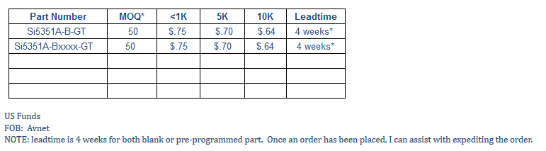
It appears that the OTP default clock value is a factory option and must be ordered through SiLabs. About to email our support group for the cost of this option. For our immediate project, this is not a show stopper but for your XMOS design, you would need to select a suitable clock value for the XMOS CPU to be clocked upon power up and then use a small I2C routine to alter the clock after this boot time.
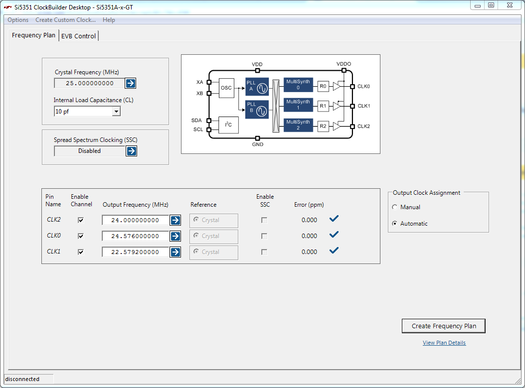
Here is the I2C register access required to produce 20.00 Mhz (0 ppm) when using a 25 Mhz crystal with the Si5351A PLL (created with the SiLabs Clock builder tool):
Code: Select all
//Register map for use with AN428 (JumpStart)
//http://www.silabs.com/clocks
//Copyright 2014 Silicon Laboratories
//**************************************************
//C-Code File version = 1
//#BEGIN_HEADER
//Date = Tuesday, May 10, 2016 11:25 AM
//File version = 3
//Software Name = Si5351 ClockBuilder Desktop
//Software version = 6.5
//Software date = June 4, 2015
//Chip = Si5351A
//Part Number = Si5351A-x-GM
//#END_HEADER
//I2C address = 0x60
/*
#XTAL (MHz) = 25.000000000
#Mode = Automatic
#PLL A
# Input Frequency (MHz) = 25.000000000
# F divider = 1
# PFD (MHz) = 25.000000000
# VCO Frequency (MHz) =  800.000000000
# Feedback Divider = 32
# Internal Load Cap (pf) = 10
# SSC disabled
#PLL B
# Input Frequency (MHz) = 0.0
# VCO Frequency (MHz) =  0.0
# Pull Range (ppm) = 0.0
#Output Clocks
#Channel 0
# Output Frequency (MHz) = 20.000000000
# Multisynth Output Frequency (MHz) = 20.000000000
# Multisynth Divider = 40
# R Divider = 1
# PLL source = PLLA
# Initial phase offset (ns) = 0.000
# Error (ppm) = 0.0000
# Powered = On
# Inverted = No
# Drive Strength = b11
# Disable State = Low
# Clock Source = b11
#Channel 1
# Powered = Off
#Channel 2
# Powered = Off
#Channel 3
# Powered = Off
#Channel 4
# Powered = Off
#Channel 5
# Powered = Off
#Channel 6
# Powered = Off
#Channel 7
# Powered = Off
#
*/

#define NUM_REGS_MAX 100

typedef struct Reg_Data{
   unsigned char Reg_Addr;
   unsigned char Reg_Val;
} Reg_Data;

Reg_Data const code Reg_Store[NUM_REGS_MAX] = {
{ 15,0x00},
{ 16,0x4F},
{ 17,0x80},
{ 18,0x80},
{ 19,0x80},
{ 20,0x80},
{ 21,0x80},
{ 22,0xC0},
{ 23,0x80},
{ 24,0x00},
{ 25,0x00},
{ 26,0x00},
{ 27,0x01},
{ 28,0x00},
{ 29,0x0E},
{ 30,0x00},
{ 31,0x00},
{ 32,0x00},
{ 33,0x00},
{ 34,0x00},
{ 35,0x00},
{ 36,0x00},
{ 37,0x00},
{ 38,0x00},
{ 39,0x00},
{ 40,0x00},
{ 41,0x00},
{ 42,0x00},
{ 43,0x01},
{ 44,0x00},
{ 45,0x12},
{ 46,0x00},
{ 47,0x00},
{ 48,0x00},
{ 49,0x00},
{ 50,0x00},
{ 51,0x00},
{ 52,0x00},
{ 53,0x00},
{ 54,0x00},
{ 55,0x00},
{ 56,0x00},
{ 57,0x00},
{ 58,0x00},
{ 59,0x00},
{ 60,0x00},
{ 61,0x00},
{ 62,0x00},
{ 63,0x00},
{ 64,0x00},
{ 65,0x00},
{ 66,0x00},
{ 67,0x00},
{ 68,0x00},
{ 69,0x00},
{ 70,0x00},
{ 71,0x00},
{ 72,0x00},
{ 73,0x00},
{ 74,0x00},
{ 75,0x00},
{ 76,0x00},
{ 77,0x00},
{ 78,0x00},
{ 79,0x00},
{ 80,0x00},
{ 81,0x00},
{ 82,0x00},
{ 83,0x00},
{ 84,0x00},
{ 85,0x00},
{ 86,0x00},
{ 87,0x00},
{ 88,0x00},
{ 89,0x00},
{ 90,0x00},
{ 91,0x00},
{ 92,0x00},
{149,0x00},
{150,0x00},
{151,0x00},
{152,0x00},
{153,0x00},
{154,0x00},
{155,0x00},
{156,0x00},
{157,0x00},
{158,0x00},
{159,0x00},
{160,0x00},
{161,0x00},
{162,0x00},
{163,0x00},
{164,0x00},
{165,0x00},
{166,0x00},
{167,0x00},
{168,0x00},
{169,0x00},
{170,0x00},
};
//End of file