Hi, i have xmos usb audio 2.0 reference design board.
I wanna chage the output format from IIS to Left Justified and connect external DAC with digital filter who accept 24bit LJ.
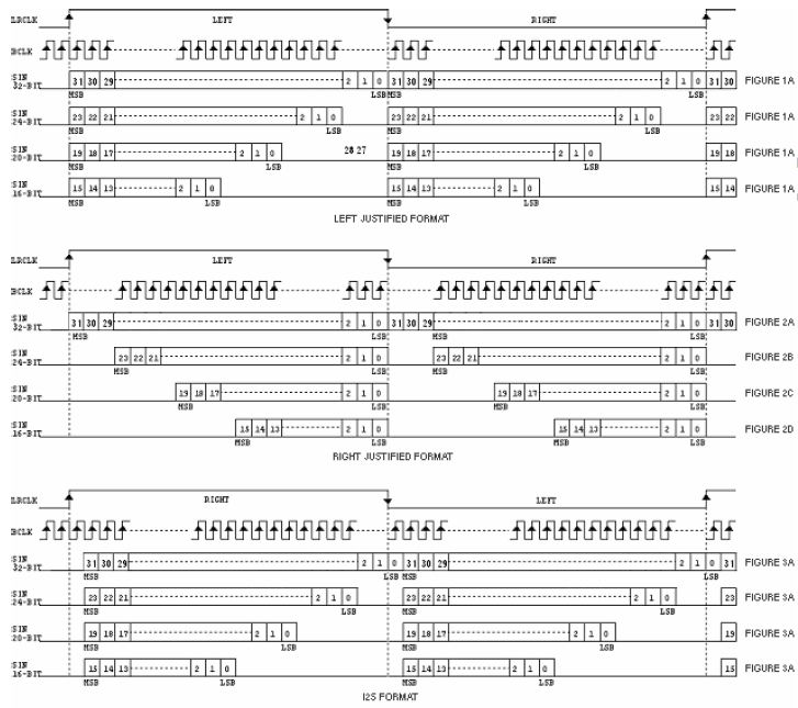
The LJ format is similar to IIS but the MSB is aligned to first falling edge of BCLK after LRCK transition. In IIS MSB is aligned with the second falling edge of the BCLK after LRCK transition.
I read the USB Audio Software-Design Guide and i notice that i can do that with modifing the main audio loop in module_usb_audio::audio.xc.
The problem is that i don't know how to implement that in the code. Can someone help me with that please!
Change output format on XMOS USB Audio 2.0 reference design
-
renegadel
- New User
- Posts: 3
- Joined: Mon Aug 17, 2015 8:14 pm
-
infiniteimprobability
 Verified
 - XCore Legend
- Posts: 1170
- Joined: Thu May 27, 2010 10:08 am
looking at the timing diagrams...
....it's almost the same thing.
The ref design left justifies (within the PCM word) data if it's 24b or 16b so all you need to do is shift by one BCLK. An easy way to do that would be to delay the LRCLK by one BCLK.
Look at the function doI2SClocks() in audio.xc. This outputs the bit patterns for the LRCLK clocked via the BCLK, least significant bit first. See page 21 of https://www.xmos.com/download/private/U ... 9.a%29.pdf to see how the ports/clocks cascade. There are cases for different BCLK:MCLK ratios. Rotate all of these values left by one bit and see if that does it...
-
renegadel
- New User
- Posts: 3
- Joined: Mon Aug 17, 2015 8:14 pm
Thank your for help.
At the begining when i read the USB Design Guide it says:
"p_lrclk is clocked by p_bclk. The port outputs the pattern 0x7fffffff followed
by 0x80000000 repeatedly. This gives a signal that has a transition one bitclock
before the data (as required by the I2S standard) and alternates between high and
low for the left and right channels of audio."
So i decide to shift the lrclk one bit clock left. In the picture below i draw the hex value for try it. Now if i understand, you suggest me to modifing bclk pattern at the desired rate. I use calculator to shift the patterns one bit left. Tommorow i will try it. Here is the code...
You do not have the required permissions to view the files attached to this post.
-
infiniteimprobability Verified
- XCore Legend
- Posts: 1170
- Joined: Thu May 27, 2010 10:08 am
Apologies - a hastily penned reply. You're right - I incorrectly advised rotating the blck. This will effectively do nothing as lrclk and data will both shift.
The key is changing the lrclk output constants. It's lsb first so rotate the entire 64b complete lrclk cycle left.
It sounds like you are on the right track and understand the task. Sorry for the confusion - let us know how you get on.
The key is changing the lrclk output constants. It's lsb first so rotate the entire 64b complete lrclk cycle left.
It sounds like you are on the right track and understand the task. Sorry for the confusion - let us know how you get on.
-
renegadel
- New User
- Posts: 3
- Joined: Mon Aug 17, 2015 8:14 pm
Hi, no problem dude, your advice let me to understand what actualy do bclk patterns. They generate bclk clock from mclk devidet in different ratios. The ratios depens from the mclk input frequency and desired fs.
Now i will try the lrck shifting and i will report it.
Now i will try the lrck shifting and i will report it.