What is the value of C10 (U6) in your power supply supervisor circuit? Leave the room for a delay cap but it should not be required. Actually may be held against you if you delay the PG output. Do not stuff C10 for initial testing unless you have a specific reason to do this.
Why not replace the linear LM317 regulator with another very efficient AP3419 for the 1v8 leg of the power supply? Otherwise, you may find that the LM317 will get warm to hot to the touch and require a heat sink varying with the expected load of this voltage rail. Just remember that in linear regulators, you will be burning the 5 volts down to the target value of 1v8 so the efficiency is quite poor and it will show in the amount of heat produced by this very old school component.
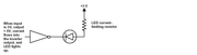
D7 may or may not light up as expected. Review the datasheet for the LED you will be using. A small trick you can use here is to insert an inverter at the output of the low voltage rail. Then at the output of the inverter, arrange to have the cathode (-) of the LED -> the current limit resistor of 390 ohms or similar -> then the anode of the LED to +5 volts.
When the 1v8 rail is LOW (ie. 0 volts or close to), the inverter output will be HIGH and the LED will remain OFF. When the 1v8 rail is not LOW, the inverter output will be LOW and cause the LED to be lit. Without this extra single gate inverter or similar, the D7 led will be most likely dim, if it works at all.
Use a single gate inverter like this one:
https://www.diodes.com/products/logic/s ... /74LVC1G04
and power it from the +5 volt rail for the LED.
You do not have the required permissions to view the files attached to this post.

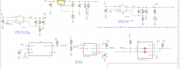 This is how the new power supply sheet is - kept the brownout and delay circuit, but changed the 3v3 and 1v Bucks for slightly larger ones.