Hello and welcome. Let me try to answer some, not all, of your questions.
1. In xhra_core.xn port "XS1_PORT_16B" is being used and named as "PORT_MCLK_COUNT". However port 1L, 1M, 1N, 1O and 1P are also being used while these overlap. Is this normal? What is the purpose of PORT_MCLK_COUNT?
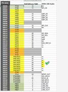
A> Best to start your review with the spreadsheet for the XCORE-200 series from here:
https://www.xmos.com/published/xcore-20 ... es-portmap
From a quick glance, do not see that port
P1L0 is overlapping the
16B port.
But, ports P1M0, P1N0, P1O0, P1P0 - do overlap.
With XMOS processors, the LEFT column of ports has priority over the respective right column(s). Think of this assignment like going to a spa for waxing. You start off with a 16 bit port for your project but then while coding, you decide to make use of a single bit port or smaller port width than the original(perhaps for a clock function which demands that only a single bit port be used). Then, rip (wax) that single bit port away from your original 16 bit port!! This means, that for example, P1M0 in the above spreadsheet, if used, is a single bit port. This will result in the 16 bit you started with missing out on P16B8 on X0 tile. So you will not see any activity during on P16B8 with a R/W to P16B on X0 tile. However, if you R/W to P1M0, then the physical pin X0D36 will be available. Note that X0D36 is noted as "X0" so this pin is on Tile[0].
2. in addition to the question above, would I be able to use XS1_PORT_4F, which also does overlap with XS1_PORT_16B? I would love having some more I/O Avaliable
A> Yes. However, if you plan to use the _16B port then the overlapped regions will be "waxed" away by the _4F ports as the _4F ports have a higher priority :) So you will be missing out of the same region on the _16B port if you access the _16B port as a group. Likewise, _4F is available as you wish but again, in groups of 4 bits at a time. In general, all bits should be in the same direction on that group (ie. input or output at the same time). There are some tricks you can do with the XCORE-200 to work around this but personally have not attempted such ideas.
3. Probably simple for those who know, but how do I make this device use UAC1 as fallback when a system doesn't support UAC2 (Especially windows XP/7/8 which do not include UAC2 drivers by default). In my XHRA-2HPA PCB setup I had a little switch users could flip to switch between those. Is the UAC code in this project smart enough to regognize when a device can support UAC2, if not, what would be the best way to read out the HIGH/LOW value of a pin on boot and changing UAC modes?
A> Not really sure about audio as we are not (yet) audio developers but it should be pretty straight forward to read out a value from a GPIO pin.
Check this document:
https://www.xmos.com/published/xmos-pro ... =B&page=26
See the details on how to input / output data.
4. Is modifying the HIGH/LOW value of a 1-bit pin like this ok?:
out port p_gpo_stream_LED = on tile[0] : XS1_PORT_1D;
p_gpo_stream_LED <: 1;
A> Yes. If your format of code raises an error then try:
Code: Select all
on tile[0]: out port p_gpo_stream_LED = XS1_PORT_1D;
The above will output a value of "1" (High @ 3v3 CMOS levels) onto the single bit port 1D which is mapped to Tile[0].
Here is a good article on working with XMOS processor (the older XS1 series) that you may like (based on the EOL startkit):
https://www.element14.com/community/gro ... e-programs
but the concepts are the same for the newer XCORE-200 series.

