I would like to use a programmable clock from Silabs to generate the 24MHz input clock for the XU216 and also the audio mclk's. I am trying to see if there is a solution for the 'first run' issue when the clock generator has not been programmed and therefore can't clock the xcore. Doing this would help reduce the BOM and has other advantages.
Is there a way to boot this device from an internal oscillator (not sure it has one) or similar so that I can program the clock generator for the first run? Alternatively, is there a way to do this over the xtag; i.e. as part of the flashing process, run a small i2c app on the xcore that programs the clock part without an external clock running?
Any ideas would be appreciated
Programming programmable clock Topic is solved
-
dlh
- Member
- Posts: 9
- Joined: Thu May 05, 2016 4:47 am
-
henkVerified
- Respected Member
- Posts: 347
- Joined: Wed Jan 27, 2016 5:21 pm
Hi dlh,
I presume you mean the xCORE200 with 'this device'; they do not support boot from an internal clock; they need some sort of clock, although it would be happy with a range of frequencies.
The XS1-A and XS1-U devices do have an internal oscillator that can be used.
Hope this helps
Henk
I presume you mean the xCORE200 with 'this device'; they do not support boot from an internal clock; they need some sort of clock, although it would be happy with a range of frequencies.
The XS1-A and XS1-U devices do have an internal oscillator that can be used.
Hope this helps
Henk
-
mon2

- XCore Legend
- Posts: 1913
- Joined: Thu Jun 10, 2010 11:43 am
Use the Si5351A or similar with an external 25 or 27 crystal (if using the small MSSOP-10 package which only supports an external crystal as the reference).
https://www.silabs.com/Support%20Docume ... 5351-B.pdf
* the lowest cost option is the MSSOP-10 device (crystal support only)
* to kick it up a notch, you could even consider a MEMS crystal to offer a shock resistance to the end device (MEMs = solid state clock source for this PLL)
* not sure if suitable for your audio project but please consult the datasheet and/or XMOS user forum for confirmation
Use a tight reference crystal with a small footprint (ie. 3225 with 10 PPM or similar). This PLL does not even require the usual loading caps on the crystal as these caps are internal (see their datasheet and ref design from Adafruit).
The Si5351 supports an one-time (OTP) boot frequency which could be your default XMOS clock value. This OTP value could be programmed by yourself or by the factory using the I2C interface (see their datasheet for more details). At this time of writing, we do not know how to program this OTP value but that is the exercise for today :) We received our evalboards just yesterday for this PLL.
To quickly evaluate this sub $1 USD PLL, review this $8 USD PCB from Adafruit:
https://learn.adafruit.com/adafruit-si5 ... t/overview
Digikey stocks these PCBs. Plenty of public documents on how to program this component on Arduino, etc.
Being I2C interface, you should be fine to apply something like a 4 pin (0.1" spacing = 2.54 mm) pin header with SDA, SCL, GROUND, RESET pins. The RESET pin can be asserted to park the XMOS CPU while you proceed to use the SDA, SCL and common ground with an external I2C bus master to program a virgin Si5351 PLL. That is the approach we are taking with our pending designs. The XMOS CPU and the external I2C master tool will have their own local power supply.
The same I2C pins (SDA, SCL) should also be mapped to local XMOS port pins so that you can alter the PLL values once the XMOS CPU has booted and is out in the field. For us, this part looks to supply all our wish list features. We know there are other suitable devices like perhaps the TI CDCE913.
From a past review, believe that the TI PLL will pass through the reference clock to the output in the absence of any special I2C programming of the local registers which should allow you to first boot the CPU.
http://www.ti.com/product/CDCE913
But SiLabs 5351 is a lower cost option.
Hope this helps.
** UPDATE **
It appears that the OTP default clock value is a factory option and must be ordered through SiLabs. About to email our support group for the cost of this option. For our immediate project, this is not a show stopper but for your XMOS design, you would need to select a suitable clock value for the XMOS CPU to be clocked upon power up and then use a small I2C routine to alter the clock after this boot time.
http://community.silabs.com/t5/Timing/h ... /true#M281
* see last post
Here is the I2C register access required to produce 20.00 Mhz (0 ppm) when using a 25 Mhz crystal with the Si5351A PLL (created with the SiLabs Clock builder tool):There is no need to burn OTP within the Si5350 device. You can order any configuration you need already burned into the device through Silicon Labs using the Clock Builder software. We do not provide OTP burn details for Si5350.
If production lead-times are a concern you should use a Si5351 device and program it with your custom configuration via I2C. This is the preferred option for fast prototyping, then locking down the configuration with burned OTP through Clock Builder for volume production.
If you will be in constant 'prototyping' mode then Si5351 is the correct device for you.
Code: Select all
//Register map for use with AN428 (JumpStart)
//http://www.silabs.com/clocks
//Copyright 2014 Silicon Laboratories
//**************************************************
//C-Code File version = 1
//#BEGIN_HEADER
//Date = Tuesday, May 10, 2016 11:25 AM
//File version = 3
//Software Name = Si5351 ClockBuilder Desktop
//Software version = 6.5
//Software date = June 4, 2015
//Chip = Si5351A
//Part Number = Si5351A-x-GM
//#END_HEADER
//I2C address = 0x60
/*
#XTAL (MHz) = 25.000000000
#Mode = Automatic
#PLL A
# Input Frequency (MHz) = 25.000000000
# F divider = 1
# PFD (MHz) = 25.000000000
# VCO Frequency (MHz) =  800.000000000
# Feedback Divider = 32
# Internal Load Cap (pf) = 10
# SSC disabled
#PLL B
# Input Frequency (MHz) = 0.0
# VCO Frequency (MHz) =  0.0
# Pull Range (ppm) = 0.0
#Output Clocks
#Channel 0
# Output Frequency (MHz) = 20.000000000
# Multisynth Output Frequency (MHz) = 20.000000000
# Multisynth Divider = 40
# R Divider = 1
# PLL source = PLLA
# Initial phase offset (ns) = 0.000
# Error (ppm) = 0.0000
# Powered = On
# Inverted = No
# Drive Strength = b11
# Disable State = Low
# Clock Source = b11
#Channel 1
# Powered = Off
#Channel 2
# Powered = Off
#Channel 3
# Powered = Off
#Channel 4
# Powered = Off
#Channel 5
# Powered = Off
#Channel 6
# Powered = Off
#Channel 7
# Powered = Off
#
*/

#define NUM_REGS_MAX 100

typedef struct Reg_Data{
   unsigned char Reg_Addr;
   unsigned char Reg_Val;
} Reg_Data;

Reg_Data const code Reg_Store[NUM_REGS_MAX] = {
{ 15,0x00},
{ 16,0x4F},
{ 17,0x80},
{ 18,0x80},
{ 19,0x80},
{ 20,0x80},
{ 21,0x80},
{ 22,0xC0},
{ 23,0x80},
{ 24,0x00},
{ 25,0x00},
{ 26,0x00},
{ 27,0x01},
{ 28,0x00},
{ 29,0x0E},
{ 30,0x00},
{ 31,0x00},
{ 32,0x00},
{ 33,0x00},
{ 34,0x00},
{ 35,0x00},
{ 36,0x00},
{ 37,0x00},
{ 38,0x00},
{ 39,0x00},
{ 40,0x00},
{ 41,0x00},
{ 42,0x00},
{ 43,0x01},
{ 44,0x00},
{ 45,0x12},
{ 46,0x00},
{ 47,0x00},
{ 48,0x00},
{ 49,0x00},
{ 50,0x00},
{ 51,0x00},
{ 52,0x00},
{ 53,0x00},
{ 54,0x00},
{ 55,0x00},
{ 56,0x00},
{ 57,0x00},
{ 58,0x00},
{ 59,0x00},
{ 60,0x00},
{ 61,0x00},
{ 62,0x00},
{ 63,0x00},
{ 64,0x00},
{ 65,0x00},
{ 66,0x00},
{ 67,0x00},
{ 68,0x00},
{ 69,0x00},
{ 70,0x00},
{ 71,0x00},
{ 72,0x00},
{ 73,0x00},
{ 74,0x00},
{ 75,0x00},
{ 76,0x00},
{ 77,0x00},
{ 78,0x00},
{ 79,0x00},
{ 80,0x00},
{ 81,0x00},
{ 82,0x00},
{ 83,0x00},
{ 84,0x00},
{ 85,0x00},
{ 86,0x00},
{ 87,0x00},
{ 88,0x00},
{ 89,0x00},
{ 90,0x00},
{ 91,0x00},
{ 92,0x00},
{149,0x00},
{150,0x00},
{151,0x00},
{152,0x00},
{153,0x00},
{154,0x00},
{155,0x00},
{156,0x00},
{157,0x00},
{158,0x00},
{159,0x00},
{160,0x00},
{161,0x00},
{162,0x00},
{163,0x00},
{164,0x00},
{165,0x00},
{166,0x00},
{167,0x00},
{168,0x00},
{169,0x00},
{170,0x00},
};
//End of file
-
dlh
- Member
- Posts: 9
- Joined: Thu May 05, 2016 4:47 am
Thanks a lot for the information.
It's a bit unfortunate that you can't program the OTP NVM, it really does not make that clear in the data sheet. So there is no way to get the Si5351 to output 'any' clock signal that could boot the xcore without it being OTP'd? It would be great if I could get any clock out of it, boot the xcore, configure the si5351, and then run.
You mentioned for my design that I could select a suitable clock value for power up, then alter the clock. Do you mean use a separate clock (not the si5351) and then have some sort of clock switching circuit? Or can this still be done all from the si5351? This is still unclear to me.
If you find out information ordering preprogrammed chips I would be great if you could pass it on. Would be interested to know what the pricing is and what sort of minimum volumes etc.
-
mon2
- XCore Legend
- Posts: 1913
- Joined: Thu Jun 10, 2010 11:43 am
Hi dlh. We too would have preferred to program the OTP inside this PLL and after soldering onto our PCB but apparently this is a guarded factory secret.
Today, we have made a formal request for this support and hope to know more likely later this week. Being a SMD part, suspecting the MOQ (min order qty) is a full tape & reel. Again, this is in our request so will share the details once we know. From the referenced post in the SiLabs user forum, the lead time for pre-programmed parts appears to be the industry standard 8-12 weeks.
Our idea for your project is to source pre-programmed parts which will start off at say 20 Mhz or whatever you find to be suitable -> allow your SPI flash to boot which will then proceed to alter this same clock to suit the project. Are you able to share which clock values you are interested in generating ? Is it a single clock or multiple values ?
Recommend that you download the referenced Clock tool from SiLabs.
====
** Update ** (there always is on my posts :)
dlh - why not consider the following idea ?
Apply an external CMOS oscillator to drive the XMOS CPU (20 or 25 Mhz or whatever is suitable for your project) to simply boot the hardware. This is a $ 0.30 USD part for 30 PPM; 3V3 volt with an OE pin. By default, you will use a pull-up on the OE pin of the oscillator to keep the part enabled during power up. Also connect this OE pin to any free XMOS GPIO pin.
Now, also add the Si5351A or any other part you find to be suitable and bond the I2C pins to the XMOS free pins with the required 2.2k PU resistors for SDA & SCL use.
The fixed external oscillator will boot your flash code -> your flash code will then proceed to prime the external PLL to your custom clock value.
The small but important detail is to how to switch between the fixed oscillator and the custom PLL clock. Suggesting to consider an idea with an external flip-flop or data latch which under code will allow you to enable the PLL output onto the XMOS clock in pin while disabling the external clock oscillator and also perform a CPU reset.
The switch over external logic would also need to support a delayed reset circuit which will trigger off the external flip-flop / data latch.
This is a convoluted idea but should be possible to achieve.
Moving along, another idea is to apply the ultra low cost EFM8 processor (about $ 0.35 USD) to prime this same Si5351A using the I2C interface and after this configuration, reset the XMOS CPU to boot your flash code. Now you may be wondering how to program the EFM8 ? Well the EFM8 uses the C2 interface which is basically a bit-banged interface which you can support using the XMOS pins. At the factory, consider to use their low cost C2 tool which is USB based. Be sure to insert the recommended resistors so that you can program at your factory and still allow the XMOS to later on upgrade the EFM8 processor code if necessary.
The lowest cost solution for the BOM may be to consider a dedicated low cost external micro to prime the selected PLL.
Just ideas but feel your pain as we too have reviewed many datasheets to date on this subject - it is the chicken or the egg debate.
-
dlh
- Member
- Posts: 9
- Joined: Thu May 05, 2016 4:47 am
I am working with the XU200 series, likely the XU216. This part requires a 24MHz clock to use the USB, and that will be constant for all configurations. The second clock output would be configurable for different MCLK values, e.g. 24.576, 22.5792 etc, to operate with different audio interfaces. The third clock will be for future use where it may be used as a second phase aligned MCLK with different frequency.
Is there a list of available pre-programmed parts by any chance? I don't foresee having the volumes worthy of the additional sourcing issues to go through the custom OTP process, but if I could older smaller quantities with 24MHz pre-programmed on the clock output I would be interested.
Is there a list of available pre-programmed parts by any chance? I don't foresee having the volumes worthy of the additional sourcing issues to go through the custom OTP process, but if I could older smaller quantities with 24MHz pre-programmed on the clock output I would be interested.
-
mon2
- XCore Legend
- Posts: 1913
- Joined: Thu Jun 10, 2010 11:43 am
Tomorrow we will review the XMOS ref designs to see how their clocks relate with the audio circuits. Suspecting that the 24 Mhz will be required to remain fixed to support the USB interface.
The Si5351A is used defined for the OTP value - from our quick use of this tool today, you proceed to validate that the part can support your clock and then a part number is assigned to your custom clock. Then the same tool can be used to issue an order for these custom clocks. Not sure what the MOQ is for the custom parts but hope to have this detail later this week or so. The tool is free to download and can confirm if your target values are possible - we tested a mix of values without any complaints from the tool. Ran out of time to actually synthesize the selected clock values but that is on our plate for tomorrow.
The Si5351A is used defined for the OTP value - from our quick use of this tool today, you proceed to validate that the part can support your clock and then a part number is assigned to your custom clock. Then the same tool can be used to issue an order for these custom clocks. Not sure what the MOQ is for the custom parts but hope to have this detail later this week or so. The tool is free to download and can confirm if your target values are possible - we tested a mix of values without any complaints from the tool. Ran out of time to actually synthesize the selected clock values but that is on our plate for tomorrow.
-
mon2
- XCore Legend
- Posts: 1913
- Joined: Thu Jun 10, 2010 11:43 am
Hi dlh. Have a response back from the local SiLabs rep. I would encourage you to contact your local Avnet branch for the same interest but here is the offer extended to our company. We have been purchasing a mix of SiLabs parts over the past number of years so there is some history and we only expect to grow in our volumes.
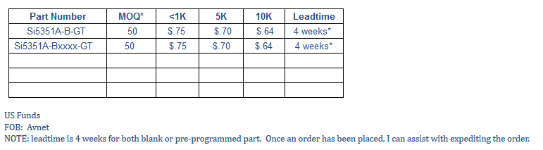
From what we understand, you will need to replace the xxxx with the custom part number generated by the Windows ClockBuilder tool by SiLabs but will confirm this detail after some lab testing.
As you can see from the quote, the MOQ is 50 pieces and a 4 week lead time for blank or pre-programmed parts. Ironically, our immediate project will use 24 Mhz (not XMOS related) so we share the same interest in this target clock oscillator value.
Very likely you should also be able to source this part with similar pricing and lead times. If not, send us a private email and will try to assist you. We are now coding and testing this PLL use and hope to have some positive notes to post later in the day using the Adafruit demo board with our custom register values.
From a quick review of the XCORE-200 audio board, there indeed is the 24 Mhz clock being fed into the XMOS device and the other clocks are for the mated audio components. XMOS used the Phaselink PLL which is also factory programmed and could be a competitive device but is a factory defined, fixed clock generator. As we are not into the audio field, not sure if there is a compelling reason to use the Phaselink brand. Perhaps someone from XMOS can confirm if there is a strict requirement on the PLL for audio use. From assorted internet pics of XMOS based boards for audio, many are using discrete oscillators (5x7 size, etc.) at the noted frequency on their PCBs.
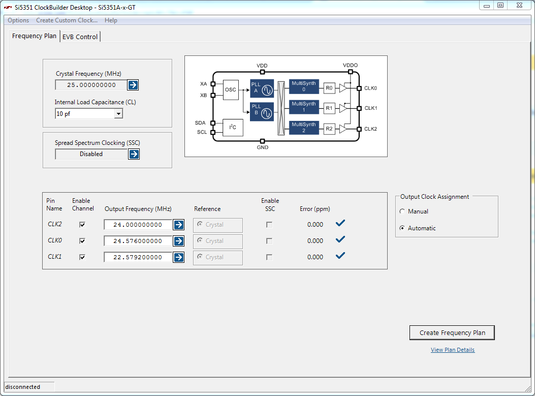
One last comment is that the SI5351A features 3 clock outputs but 2 internal PLLs. Be sure that you can 'dial up' the 24 Mhz for CLK0, custom1 for CLK1, custom2 for CLK3 using the reference 25 or 27 Mhz crystal. Should be ok but best to confirm with their Windows ClockBuilder based tool.
Just ran your values through their tool and the results look promising:
Reference:
http://www.silabs.com/Support%20Documen ... Si5351.zip
From what we understand, you will need to replace the xxxx with the custom part number generated by the Windows ClockBuilder tool by SiLabs but will confirm this detail after some lab testing.
As you can see from the quote, the MOQ is 50 pieces and a 4 week lead time for blank or pre-programmed parts. Ironically, our immediate project will use 24 Mhz (not XMOS related) so we share the same interest in this target clock oscillator value.
Very likely you should also be able to source this part with similar pricing and lead times. If not, send us a private email and will try to assist you. We are now coding and testing this PLL use and hope to have some positive notes to post later in the day using the Adafruit demo board with our custom register values.
From a quick review of the XCORE-200 audio board, there indeed is the 24 Mhz clock being fed into the XMOS device and the other clocks are for the mated audio components. XMOS used the Phaselink PLL which is also factory programmed and could be a competitive device but is a factory defined, fixed clock generator. As we are not into the audio field, not sure if there is a compelling reason to use the Phaselink brand. Perhaps someone from XMOS can confirm if there is a strict requirement on the PLL for audio use. From assorted internet pics of XMOS based boards for audio, many are using discrete oscillators (5x7 size, etc.) at the noted frequency on their PCBs.
One last comment is that the SI5351A features 3 clock outputs but 2 internal PLLs. Be sure that you can 'dial up' the 24 Mhz for CLK0, custom1 for CLK1, custom2 for CLK3 using the reference 25 or 27 Mhz crystal. Should be ok but best to confirm with their Windows ClockBuilder based tool.
Just ran your values through their tool and the results look promising:
Reference:
http://www.silabs.com/Support%20Documen ... Si5351.zip
-
dlh
- Member
- Posts: 9
- Joined: Thu May 05, 2016 4:47 am
I really appreciated the time you have taken with your responses, has helped a lot. The MOQ is actually much lower than I thought it would be, which is great.
I had a look at the Phaselink part and it looks like the main feature is 30-70ps period jitter compared to 100ps for the Si5351. While lower is better, the it won't be the limiting factor in in audio quality and so the Si5351 is good enough. Also, they were recently bought by Microchip and it is difficult to source the part. The Microchip page for this part (http://www.microchip.com/wwwproducts/en/PL611-01) has a 'Buy It Now' button but clicking on it leads to a page which states "This Device is currently not available for Purchase Online. No products found."
So I think I will stick with the Si5351 as it meets my needs. Curious to know what oscillator you have selected? I am looking through http://www.silabs.com/Support%20Documen ... /AN551.pdf and will probably use the 7M-27.000MEEQ part, just because it's the 'best' and is recommended. Unfortunately, it is more expensive than the Si5351 part!
-
mon2
- XCore Legend
- Posts: 1913
- Joined: Thu Jun 10, 2010 11:43 am
Hi dlh. Glad to help where we can - as long as it is not a conflict of interest which it is not.
We source our crystals and oscillators directly from China. Been there many times and attended countless trade shows - after some weeding of the bad from the good, here is a sample of what you should be paying (however with a MOQ of a full T&R):
Crystal Resonator SMD3225 25.000MHz +/-10ppm / +/-10ppm / -20`+70C / 15pF / 50 ohms
Aging is +/-3ppm for the first year
Unit price: USD0.130 FOB shenzhen
Lead time: 3-4 weeks
Packing: tape & reel
MPQ: 3K pcs / reel
Openly, you can source for a bit less but the quality may vary. If you are interested, contact details are:
Foina Yeung
TEL: 86-186 8242 0160
e-mail: foinayeung@hotmail.com
skype: foina-chinafronter
Company is China Fronter and we have used very high volumes of their parts over the past 15 years with zero defects. Another option is to consider a new vendor we have approved and that is WTL Crystal.
Lori Chang
Sales Manager
Shenzhen WTL Electronic Technology Co., Ltd
T: +86-755-8267 7582 ext: 801 M: +86 13530420550
E:wtl001@wtlcrystals.com Skype:wtl-delly
W : http://www.wtlcrystals.com Alibaba: http://wtlcrystals.en.alibaba.com
Quote from WTL on the same:
16pF,+/-30ppm/ -20°C - 70°C +/- 20ppm
25.0000MHz
MOQ: 1K
0.092USD each
Lead time: 4 weeks (often is less)
Today we have validated the Adafruit PCB with the Si5351A component (10 pin MSOP). Do note that oscillator is NOT an option with this PLL but rather only a crystal. For this reason, your part sourcing should be a lower cost (even if using Digikey / Mouser).
We have the 25 Mhz 10 ppm crystals in stock but have not yet validated if the capacitive load value is suitable for use with the Si5351A - still to be confirmed. Our interest is to use the 25 Mhz crystal value since it is so common for other projects including our pending Ethernet XMOS designs (Atheros PHY uses 25 Mhz).
The footprint for the selected crystal is 3225 = 3.2 x 2.5 mm.
If it makes business sense, consider to source a full T&R (1K pieces) from Asia (China Fronter or WTL) or if you need a few pieces, we can ship to you from here (Canada) but shipping may be more expensive than the parts :)
Next on the things to do list is to confirm if the in stock crystals are suitable.
BTW : Today we did successfully program our FPGA as an I2C bus master -> programmed the Si5351A to generate:
8 khz
1.00 Mhz
1.8432 Mhz
5.0 Mhz
each frequency worked fine using the CLK0 output (other 2 were disabled on the demoboard).