
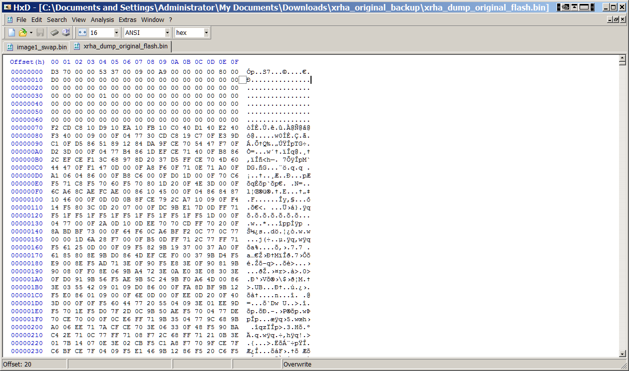
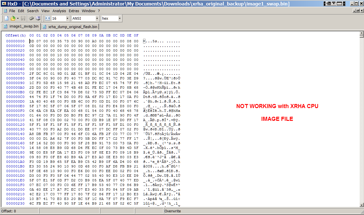
Your posted image appears to be reversed to what is stored inside the original flash memory present on the official XRHA demo board. See below to compare.
Invested all of Friday for this review and clearly see many improvements that can be made for production. For starters, took close to 8 minutes to completely read out the contents of the original XRHA flash memory device using the standard SPI command. Respectively the same to write the contents onto a blank flash device. This exercise was to R/W the entire density of the IS25LQ016B memory device - not to exclude any memory regions. On Monday we will confirm if the process was a success or not but feeling very confident that we have cloned the original flash device and enabled the QE bit. For this review, we did not use the XFLASH tool to enable the QE bit so still researching on how to properly use the QSPI support within this tool. The QE bit was enabled using our code. The use of the XFLASH tool can be improved with examples on how to use this fairly powerful tool. We did manage to create a custom definition for our QSPI flash device and did interface our definition with the xTimeComposer to flash our blinky code into this new memory IC.
We are moving to design a production grade, yet affordable programming jig using an XMOS processor for this purpose. Will share more details next week as we close the design.
Try to alter your flash image as noted above to match the format of the original flash device and post your revised status. If still not working, we can send out a copy of the flash (after testing against our original XMOS board) to your side. ETA is Monday for 'final' testing of the cloned image.