Thanks for all the help! I will be able to use all the advice given to solve my problem. However, I have run into a even bigger problem that has to be tackled first haha. It looks like I will need a configurable external clock after all so I will be using mons2's adafruit breakout board although I am not sure how I will control it with the startkit (the libraries are all tailored to arduino).
Thanks again!
STARTkit and external clock Topic is solved
-
dsdanielko
- Active Member
- Posts: 33
- Joined: Sat Mar 12, 2016 3:12 pm
-
mon2

- XCore Legend
- Posts: 1913
- Joined: Thu Jun 10, 2010 11:43 am
Let me try to assist to get you going while this topic is fresh on my mind. Have this PLL working very well on our FPGA and low cost micro. Time permitting, can review porting onto StartKit but do not wish to make a promise on the timeline.
The Adafruit board with the Si5351A is available through Digikey and perhaps others for under $10 USD + shipping. Keep in mind that the ref clock is 25 Mhz for this finished adapter board. The chip supports only 25 Mhz or 27 Mhz for the ref crystal to generate any clock value you desire.
The 10 pin package of this Si5351A is strictly requiring a local crystal (not oscillator). Also, you must inform the clock builder s/w (see later in this post) of the ref crystal value using their pull-down menu. In error, we left at 27 Mhz and all of our desired clocks were skewed to be too low.
Download the SiLabs configuration utility for this PLL:
http://www.silabs.com/Support%20Documen ... Si5351.zip
Download and install and generate some clock values to get wet with this register generating tool. That is, after you create the target clock value with 0 PPM, select the CREATE FREQUENCY PLAN button to verify the target clock value is possible. To date, could not find a value this thingy could not support !! They really designed this part well.
Next, review the registers used to achieve the target clock value by selecting the Options -> Save C code header file. Then open this target file to understand which registers actually need to be saved by the I2C Bus Master (XMOS code). We found that most of the registers remain static - use this to your advantage to limit the array of register values to be written. We used loops to write the static locations and this will shrink your code size.
The hardware is I2C bus (also known as SMBUS) and therefore you need to find 2 pins on the XMOS StartKit for this task. Apply a pull-up resistor to each of these pins (2.2k to 10k is fine with this single load). Connect the pull-up to 3v3 (sourced from the XMOS board).
Recommendation for the I2C pins are:
port I2C_SCL = XS1_PORT_1E; //I2C clock
port I2C_SDA = XS1_PORT_1H; //I2C data
Use the above with the XMOS I2C library although there are other methods since in summary, this is just bit-banging out serial data and a serial clock.
Review this document and download the related library for the I2C Master:
https://www.xmos.com/download/private/l ... rc1%29.pdf
and
https://www.silabs.com/Support%20Docume ... /AN619.pdf
Start with a simple 'ping' to the Si5351A to confirm your hardware and software upto this point is operational. Recommend to read and write to say register 0x03 (Clock Enable register) to validate that your XMOS code and mated PLL circuit are working well together.
If your budget permits, consider to source an I2C bus analyzer like Total Phase Beagle or similar. Such tools are priceless to observe the data traffic bouncing to / from your target I2C device. However, in theory, if the XMOS library is coded properly, you could skip the need for this tool.
Chime back if you need help or have any other questions.
-
dsdanielko
- Active Member
- Posts: 33
- Joined: Sat Mar 12, 2016 3:12 pm
So do I need to buy the crystal separately? I was under the impression that it already had the crystal onboard.
I spent the day trying to transfer the si5351 arduino libraries into xmos but was having a hard time. This is my very first embedded system project so I was feeling a little out of my depth. So by studying the registers I can just create xC codes to overwrite them (utilising the i2c master lib), correct?
Thanks
-
mon2
- XCore Legend
- Posts: 1913
- Joined: Thu Jun 10, 2010 11:43 am
1) The Arduino board is complete. Just apply power (BTW = 5 volts as this PLL board contains an onboard 3v3 regulator to lower the voltage). If in doubt on any such detail - DO NOT power up and chime back for assistance. Best to be sure before taking any such risks.
That is, the PLL operates from 3v3 but the designer of the board has an onboard 5 volt to 3V3 regulator to be more friendly. The I2C interface pins will remain to swing at 3V3 between XMOS and this PLL IC.
2) Connect the 3 pins to your XMOS board:
a) I2C_CLK with a pull-up resistor (not super critical but 2.2k is the industry value but up to 10k is ok)
b) I2C_SDA with a pull-up resistor (not super critical but 2.2k is the industry value but up to 10k is ok)
c) ground to keep common across of power circuits
Personally not an Arduino coder but does not hurt to review. Recommend to just focus on the I2C library from XMOS and try to read register 0x03 - should be 00 by power up default -> then use the XMOS library to write a value of say 0x55 and read back to verify. If it matches, ok to proceed to prime the PLL registers.
Will be happy share some register values but they are extracted from the SiLabs tool. That is, if you follow the notes from SiLabs, the PLL will spark up and spit out the desired clock.
Do you have access to an oscilloscope or a meter with a frequency counter ? That will help here. In a pinch, the Saleae tool (or similar) will help:
http://www.ebay.com/itm/24MHz-8-Channel ... SwyQtV1vOO
We started with a low clock output value to validate with our meter before digging out the scope and confirm the clock to be very clean up to 20 Mhz then stopped our review and proceeded to write the firmware.
Another comment which may not be relevant but this PLL contains an OTP (one time programmable) for a power up clock value. BUT you cannot program this configuration - only the factory can. Likely not a deal breaker but thought to share. For pennies more (if that), the factory will program the part with your desired OTP value but you can of course change to any value using the I2C interface.
Summary:
a) forget the Arduino stuff for now
b) review the I2C library docs on how to use and place the sample library into the STartKit and start compiling
c) fix any potential coding errors during the import
d) connect to the Adafruit board as noted and then R/W using the Si5351A I2C address (each chip will have its own I2C address that must be used by the XMOS code) to index the IC.
e) then proceed to R/W your register(s) using the same indexed IC.
Hope this helps.
================
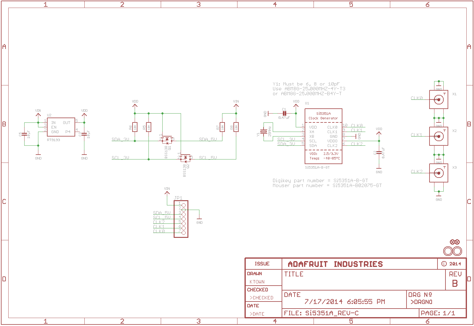
Sorry - did not answer your question about the crystal. Nothing else is required. The crystal is pre-soldered by Adafruit. I only mentioned it because if you plan to make a custom PCB with this PLL then be sure to note that you MUST use an external crystal with the PLL. Often, PLL ICs support crystals or oscillators (crystal with some internal parts in a single package). We prefer oscillators since they are guaranteed to power up and be working by the factory but they cost more. However, Si5351A in the 10 pin package strictly notes that only crystals can be used. That is what Adafruit did and applied a local 25 Mhz crystal. Do review the Adafruit schematic for this board.
https://cdn-learn.adafruit.com/assets/a ... 1407873628
That is, the PLL operates from 3v3 but the designer of the board has an onboard 5 volt to 3V3 regulator to be more friendly. The I2C interface pins will remain to swing at 3V3 between XMOS and this PLL IC.
2) Connect the 3 pins to your XMOS board:
a) I2C_CLK with a pull-up resistor (not super critical but 2.2k is the industry value but up to 10k is ok)
b) I2C_SDA with a pull-up resistor (not super critical but 2.2k is the industry value but up to 10k is ok)
c) ground to keep common across of power circuits
Personally not an Arduino coder but does not hurt to review. Recommend to just focus on the I2C library from XMOS and try to read register 0x03 - should be 00 by power up default -> then use the XMOS library to write a value of say 0x55 and read back to verify. If it matches, ok to proceed to prime the PLL registers.
Will be happy share some register values but they are extracted from the SiLabs tool. That is, if you follow the notes from SiLabs, the PLL will spark up and spit out the desired clock.
Do you have access to an oscilloscope or a meter with a frequency counter ? That will help here. In a pinch, the Saleae tool (or similar) will help:
http://www.ebay.com/itm/24MHz-8-Channel ... SwyQtV1vOO
We started with a low clock output value to validate with our meter before digging out the scope and confirm the clock to be very clean up to 20 Mhz then stopped our review and proceeded to write the firmware.
Another comment which may not be relevant but this PLL contains an OTP (one time programmable) for a power up clock value. BUT you cannot program this configuration - only the factory can. Likely not a deal breaker but thought to share. For pennies more (if that), the factory will program the part with your desired OTP value but you can of course change to any value using the I2C interface.
Summary:
a) forget the Arduino stuff for now
b) review the I2C library docs on how to use and place the sample library into the STartKit and start compiling
c) fix any potential coding errors during the import
d) connect to the Adafruit board as noted and then R/W using the Si5351A I2C address (each chip will have its own I2C address that must be used by the XMOS code) to index the IC.
e) then proceed to R/W your register(s) using the same indexed IC.
Hope this helps.
================
Sorry - did not answer your question about the crystal. Nothing else is required. The crystal is pre-soldered by Adafruit. I only mentioned it because if you plan to make a custom PCB with this PLL then be sure to note that you MUST use an external crystal with the PLL. Often, PLL ICs support crystals or oscillators (crystal with some internal parts in a single package). We prefer oscillators since they are guaranteed to power up and be working by the factory but they cost more. However, Si5351A in the 10 pin package strictly notes that only crystals can be used. That is what Adafruit did and applied a local 25 Mhz crystal. Do review the Adafruit schematic for this board.
https://cdn-learn.adafruit.com/assets/a ... 1407873628
-
mon2
- XCore Legend
- Posts: 1913
- Joined: Thu Jun 10, 2010 11:43 am
Here is the working source code for use with StartKit (or any other XMOS target) to configure the SiLabs Si5351A PLL. Have placed some comments into the source code. The posted code will configure the Adafruit PCB to generate 18.432 Mhz but you can easily alter this clock value to suit using the SiLabs Clock Builder tool.
After we read up on Github, will post there for easier access. For now, this code is hosted on our company server.
Entire project and compiled binary for use with the XMOS StartKit:
http://www.softio.com/xmos/I2C_SI5351A_ ... xample.zip
Chime back if you have any questions.
Enjoy !
* as the flamingo would say from the Lowe's commercial
Kumar
After we read up on Github, will post there for easier access. For now, this code is hosted on our company server.
Entire project and compiled binary for use with the XMOS StartKit:
http://www.softio.com/xmos/I2C_SI5351A_ ... xample.zip
Code: Select all
// Copyright (c) 2016, XMOS Ltd, All rights reserved
//
// Author  : K. Bhatia (Mon2)
// Company : Axxon Computer Corporation
// Version : 1.0
// Compile Date : 06-02-2016
//

#include <xs1.h>
#include "i2c.h"
#include "debug_print.h"

// I2C interface ports
port p_scl = XS1_PORT_1E; // X0D12 on J7 of StartKit (3rd hole) & apply a 2.2k to 10k pull up to 3V3 (I2C spec)
port p_sda = XS1_PORT_1F; // X0D13 = Square PCB pad on J7 of StartKit (first hole) & apply a 2.2k to 10k pull up to 3V3 (I2C spec)


// Connect 3V3    from XMOS StartKit pad to Vin of Adafruit Si5351A PCB (Digikey sells these finished PLL PCBs)
// Connect Ground from XMOS StartKit pad to Ground of the Si5351A moule PCB
//
// Connect D12 pad of StartKit J7 (I2C_SCL) to I2C_SCL of Si5351A PCB
// Connect D13 pad of StartKit J7 (I2C_SDA) to I2C_SDA of Si5351A PCB
//
// This is important since the XMOS port pins are NOT, repeat NOT 5V0 tolerant !!
//
// Use the SiLabs Clock Builder tool to generate the C-code Header file to generate the PLL values shown below
//
// Be sure to use 25 Mhz as the ref clock since Adafruit boards are fitted with a 25 Mhz crystal !!!
//


// SI5351A register address defines
#define SI5351A_I2C_ADDR 0x60
#define SI5351A_CLKx_DIS 0x03
#define SI5351A_Reg16    0x16

unsigned char pll_reg[31][2] = {

// PLL values are 31 entries x 2 = 62 bytes which are dynamic to the selected clock value
// the static values are hard-coded in the write_to_pll routine

        //18.432 Mhz
        { 15,0x00},
        { 16,0x4F},
        { 17,0x80},
        { 18,0x80},
        { 19,0x80},
        { 20,0x80},
        { 21,0x80},
        { 22,0x80},
        { 23,0x80},
        { 24,0x00},
        { 25,0x00},
        { 26,0x0C},
        { 27,0x35},
        { 28,0x00},
        { 29,0x0C},
        { 30,0x02},
        { 31,0x00},
        { 32,0x01},
        { 33,0x96},
        { 34,0x00},
        { 35,0x00},
        { 36,0x00},
        { 37,0x00},
        { 38,0x00},
        { 39,0x00},
        { 40,0x00},
        { 41,0x00},
        { 42,0x00},
        { 43,0x01},
        { 44,0x00},
        { 45,0x11}

        /*
        // 14.7456 Mhz (25 Mhz as ref xtal)
        { 15,0x00},
        { 16,0x4F},
        { 17,0x80},
        { 18,0x80},
        { 19,0x80},
        { 20,0x80},
        { 21,0x80},
        { 22,0x80},
        { 23,0x80},
        { 24,0x00},
        { 25,0x00},
        { 26,0x3D},
        { 27,0x09},
        { 28,0x00},
        { 29,0x0C},
        { 30,0x27},
        { 31,0x00},
        { 32,0x35},
        { 33,0xA1},
        { 34,0x00},
        { 35,0x00},
        { 36,0x00},
        { 37,0x00},
        { 38,0x00},
        { 39,0x00},
        { 40,0x00},
        { 41,0x00},
        { 42,0x00},
        { 43,0x01},
        { 44,0x00},
        { 45,0x16}
        */

        /*
        // 5 Mhz
        { 15,0x00},
        { 16,0x4F},
        { 17,0xA3},
        { 18,0xA3},
        { 19,0x80},
        { 20,0x80},
        { 21,0x80},
        { 22,0xC0},
        { 23,0x80},
        { 24,0x00},
        { 25,0x00},
        { 26,0x00},
        { 27,0x01},
        { 28,0x00},
        { 29,0x0D},
        { 30,0x00},
        { 31,0x00},
        { 32,0x00},
        { 33,0x00},
        { 34,0x00},
        { 35,0x00},
        { 36,0x00},
        { 37,0x00},
        { 38,0x00},
        { 39,0x00},
        { 40,0x00},
        { 41,0x00},
        { 42,0x00},
        { 43,0x01},
        { 44,0x00},
        { 45,0x49},
        */
};


// sourced from AN10084
void delay(void)
{
    timer t;
    unsigned int start_time, end_time;
  /**
    How to wait for a period of time using a timer
    ----------------------------------------------

    Timers can be used to pause a task until a certain amount of time has
    passed. First input the current time from the timer:
  **/

    t :> start_time;
  /**
    Next compute the time you want the task to wait until, by adding the
    desired number of timer ticks to the start time:
  **/

    end_time = start_time + 500;
  /**
    Finally use the following statement to wait for end_time to be
    reached:
  **/

    t when timerafter(end_time) :> void;
}


// sourced from AN00156
void si5351a_pll_configuration(client interface i2c_master_if i2c) {

  unsigned int i;

  // Configure SI5351A

  // Disable all outputs setting CLKx_DIS high
  // Write Reg3 = 0xFF
  i2c.write_reg(SI5351A_I2C_ADDR, SI5351A_CLKx_DIS, 0xff);

  delay();

  //  Power down all output drivers
  //  Write Reg16 – Reg 23 = 0x80
  i2c.write_reg(SI5351A_I2C_ADDR, SI5351A_Reg16, 0x80);

  // prime the unique PLL values for our desired clock
  for (i=0; i<=30;i++)
      i2c.write_reg(SI5351A_I2C_ADDR, pll_reg[i][0], pll_reg[i][1]);

  //  Write Reg46 – Reg92 = 0
  for (i=46; i<=92;i++)
      i2c.write_reg(SI5351A_I2C_ADDR, i, 0);

  //  Write Reg149 – Reg170 = 0
  for (i=149; i<=170;i++)
      i2c.write_reg(SI5351A_I2C_ADDR, i, 0);

  // Apply soft reset
  // Write Reg 177 = 0xAC
  i2c.write_reg(SI5351A_I2C_ADDR, 177, 0xac);


  // Enable SI5351A (CLK0 only)
  // Write Reg 3 = 0xFE = Enable CLK0 (only)
  i2c.write_reg(SI5351A_I2C_ADDR, SI5351A_CLKx_DIS, 0xfe); // note that a '0' turns the PLL output ON !!

  delay();

}   // End PLL_configuration


int main(void) {
  i2c_master_if i2c[1];
  par {
    i2c_master(i2c, 1, p_scl, p_sda, 10);
    si5351a_pll_configuration(i2c[0]);
  }
  return 0;
}
Enjoy !
* as the flamingo would say from the Lowe's commercial
Kumar
-
dsdanielko
- Active Member
- Posts: 33
- Joined: Sat Mar 12, 2016 3:12 pm
Oh thanks so much but I spent this morning translating the arduino library into xC haha.
It was a pain as the libraries are coded in C++ with lots of classes and I don't know how to integrate C++ class functions into xC so I converted the classes into C structs which are much easier to port into xC).
I can't test it right now since I need to go into university tomorrow to use an oscilloscope.
I also just got the board in the mail too so I'm excited to test it out.
Hopefully my code works but if it doesn't I'll gladly use yours!
PS. is there a command line version of the clockbuilder? Ideally I would like to make the whole process 'one click' so the calculated pll parameters are transferred to the startkit automatically
-
mon2
- XCore Legend
- Posts: 1913
- Joined: Thu Jun 10, 2010 11:43 am
Not aware of any command line version of the Clock Builder tool but you could review their datasheet for this component and follow the recommended algorithms to generate the clock register values on the fly. At this time, the Clock Builder is a great tool to validate the component is sound and that we can support our target (for now fixed) clock values.
Also, need to stress that power the Adafruit board from 3V3 (not 5V0 as earlier stated by my post). The reason being that XMOS is 3V3 tolerant only. We have been coding using 3V3 only with this PLL board.
Have fun !
Also, need to stress that power the Adafruit board from 3V3 (not 5V0 as earlier stated by my post). The reason being that XMOS is 3V3 tolerant only. We have been coding using 3V3 only with this PLL board.
Have fun !
-
dsdanielko
- Active Member
- Posts: 33
- Joined: Sat Mar 12, 2016 3:12 pm
Ok the translations worked first time.
Just gotta think of algorithms for getting divider values now.
Thanks for the help mons2
Just gotta think of algorithms for getting divider values now.
Thanks for the help mons2
-
mon2
- XCore Legend
- Posts: 1913
- Joined: Thu Jun 10, 2010 11:43 am
Excellent ! It is always nice when projects work :)
We too need to review a more dynamic method to select any clock output on the fly.
Found this post which looks suitable for the task:
http://qrp-labs.com/synth/oe1cgs.html
http://qrp-labs.com/images/synth/demo4/oscillator.ino
We too need to review a more dynamic method to select any clock output on the fly.
Found this post which looks suitable for the task:
http://qrp-labs.com/synth/oe1cgs.html
http://qrp-labs.com/images/synth/demo4/oscillator.ino
SetFrequency(freq)...Sets "freq" [in Hz] as output frequency
-
xchips
- Active Member
- Posts: 51
- Joined: Wed Jun 22, 2016 8:08 am
@mon2.
Hi, mon2, I want to use Si5351A on my USB Audio project. After reading what you posted about Si5351A. I have a question:
I want to output a 24MHz clk for the system clk of XCORE by NVM field at the first run. But there is a question for me:
Will this 24MHz be changed (or stopped) while the other clks are being programmed? In your code:
This will apply a reset for PLLA and PLLB.
I think the XCORE will stop too when the 24MHz clock stops.
Thanks in advice!
Hi, mon2, I want to use Si5351A on my USB Audio project. After reading what you posted about Si5351A. I have a question:
I want to output a 24MHz clk for the system clk of XCORE by NVM field at the first run. But there is a question for me:
Will this 24MHz be changed (or stopped) while the other clks are being programmed? In your code:
Code: Select all
  // Apply soft reset
  // Write Reg 177 = 0xAC
i2c.write_reg(SI5351A_I2C_ADDR, 177, 0xac);I think the XCORE will stop too when the 24MHz clock stops.
Thanks in advice!