So I am currently redesigning the Audio platform PCB, and I will be using 5volts input to the whole board ( There will be no analogue in/out no outputs at all, no ethernet, adc, dac). ON the usb sheet there is current and over voltage protection for when the usb is in Host mode (from what understood). So I am wondering if i can just remove those, as it will only be used to take audio from the PC (always a client). Have I the right idea or am I misunderstanding.
Option 2 would be keeping the outputs limiters, and attaching the PSU_EN to a a similar logic as the 12to5 volt pow sup but with a 5volt input, but then i'd have to solder more (grrrrr)
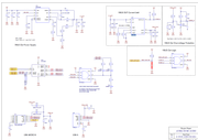
Schematic for the audio platform usb sheet
Removing the Vbus out Topic is solved
-
- Experienced Member
- Posts: 78
- Joined: Thu Mar 08, 2018 2:44 pm
-
- XCore Legend
- Posts: 1913
- Joined: Thu Jun 10, 2010 11:43 am
To be clear, can you post the vbus circuit? Which reference kit design are you using?
-
- XCore Legend
- Posts: 1913
- Joined: Thu Jun 10, 2010 11:43 am
So you will power this design with +5 volts supplied by the PC USB connector?
If yes, then yes the extra circuits can be streamlined but confirm:
a) is the host PC able to supply the current demanded by your end design? The max current you can source from USB 2.0 (black insulator) ports is 500 mA. For USB 3.0 (blue insulator) ports is 900 mA.
b from our review on USB ports about 2 years ago, we found that most add-on host adapters offer zero protection against current limits (we bought off Amazon). So if you took a screwdriver and shorted VBUS on the add-on adapter's USB port, after a spark, you can expect that port to be damaged and the only form of protection will be the PCB trace thickness acting like a fuse. Useless design for such add-on adapters.
Your mileage may vary with the motherboards which may or may not offer polymer fuse protection for current limits. Even polymer fuses are lame as they derate as they are used for protection but they are better than not having such protection.
c) even if you will use the VBUS rail from your host PC to power your product, place a USB load switch like AP2331 to allow for the soft start to limit in rush current and also offers reverse voltage protection, over voltage protection and does not derate while it protects the downstream devices.
The AP2331 is intended to pass through 200 mA downstream and is under $ 0.10 USD each so very well worth the cost. This device is showing in the datasheet to trigger (shut off the power) @ 400-500mA current range.
Other versions are available for higher current pass through.
d) being USB related, be sure to review the Intel article on USB HS design (480 Mbps) for PCB layout. Respectively, these USB 2.0 HS traces are required to be highlighted to your PCB shop to be impedance controlled @ 90 ohms else you can / will face field issues on the operation of your end product. No PCB stubs and the USB traces must be length matched. You can review the thread from hamtam on this topic.
http://www.xcore.com/viewtopic.php?f=21&p=32847#p32847
e) add USB 2.0 HS compliant ESD protection devices onto the USB connector. An excellent vendor is Socay (Shenzhen) whom we have used for many years with excellent results. You can source the same footprint parts in small qty from Digikey (Bourns, Littlefuse, etc.) and then consider this offshore supplier to lower your BOM costs. Same for an EMI filter for USB 2.0 HS. Offshore supplier for a reduced cost is Kingcore (Taiwan).
f) For the USB connector, best to consider local suppliers first to be confident the contact tension is correct. We did have a bad experience on this sourcing and the sourced parts were not used in live production as the connector felt too loose for field use. The vendor rebuilt the entire batch of parts. A good supplier for USB connectors is Homyet but start with local suppliers and then request for a drop in replacement from their side. We found the tension fit to be excellent with their connectors. I think the real issue is that unless you can properly define all aspects of the component you wish to source, then the vendor is free to offer what they have - perhaps from other customer runs.
SHEN ZHEN HOMYET PARTS ELECTRONICS CO.,LTD
Seven Zhang /+86 15112386375
Tel:+86-755-83676824 29768399
Fax:+86-755-83676835 27888655
Add:306,E Building ,HuaChuangDa Industrial Park,Bao'an 42 District,Shenzhen , Guangdong Province,CHINA
Mail: seven@homyet.com; 2355400604@qq.com
Web:www.homyet.com
QQ: 2355400604
skype: sevenzhang07@hotmail.com
WhatsApp:+86 15112386375
You do not have the required permissions to view the files attached to this post.
-
- Experienced Member
- Posts: 78
- Joined: Thu Mar 08, 2018 2:44 pm
Wow, you're amazing.
What do you think about the 2.5Vs in the circuit. I want to remove them, but in the documentation I was not able to see if the 2.5V are used for anything than the DAC (which will not be used in my project). They do go into the XMOS chip, and I will keep them if I do not find a definite answer. Any idea how I can verify this>?
-
- XCore Expert
- Posts: 580
- Joined: Thu Nov 26, 2015 11:47 pm
In addition to the DAC, the other reason for the 2.5V supply in the MC Audio platform is for the IO voltage for Ethernet PHY SMI and RGMII interfaces (VDDIOT). So you can replace it with 3.3V if you don't have Ethernet.
-
- XCore Legend
- Posts: 1913
- Joined: Thu Jun 10, 2010 11:43 am
Agree with @akp. The 2v5 is an IO rail voltage so that you remain compatible with +2v5 connected devices. That is the Ethernet PHY and DAC. You can change this voltage rail to be 3v3 which is more common but be sure your mated devices are friendly with 3v3.
-
- XCore Addict
- Posts: 144
- Joined: Wed Jun 29, 2016 8:59 am
@mon2: Can I also replace the 2v5 supply with a 3v3 for all processors of the XU series? I use the XUF216-512-TQ128. That would be great, because it reduces my bom.
-
- XCore Legend
- Posts: 1913
- Joined: Thu Jun 10, 2010 11:43 am
hi. yes, you can use +3v3 for VDDIOT if your target interface is also able to support +3v3 I/O swing. If I recall correctly, the Ethernet Gigabit PHY demanded the use of the +2v5 rail so for that reason, this I/O rail on the XMOS CPU had to be powered @ +2v5 volts. In short, this feature allows for a level translation that is safe for the external and internal architectures of the mated devices.
You do not have the required permissions to view the files attached to this post.
-
- XCore Addict
- Posts: 144
- Joined: Wed Jun 29, 2016 8:59 am
Thx mon2. Now, I have understood the power suppling of VDDIOT. The final clue gave me the port map doc (https://www.xmos.ai/file/xcore-200-devices-portmap/). The column "I/O rail" explains, which pin is connect to which vdd source. It's so simple.