Hi
I have a long-term hobby project, to build a robot that can do something that is very boring for a human - placing SMD components.
I have built a machine from scratch, including the electronics and software. Everything is open-source - but is work in progress.
So far, the explorer KIT has been used with different daughter cards connected to it.
I would appreciate if someone could check my XTAG, Xlink connections etc. on the new "CPU" board. The board is intended to be connected in a galvanic isolated XLink network, for an example like this
https://github.com/lilltroll77/XMOS-XU2 ... etwork.pdf or
https://github.com/lilltroll77/XMOS-XU2 ... etwork.pdf
The networks above run in the xTIMEcomposer simulator without errors.
The PCB's can either be populated as a hub with USB, and a Gigabit ethernet shield, or as a network node that runs
FOC SVPWM for BLDC (Field-oriented control combined with Space Vector Pulse Width Modulation for Brushless DC Motors) by connecting a daughter card/shield power by the 48V motor rail.
USB ground will be isolated from power ground.
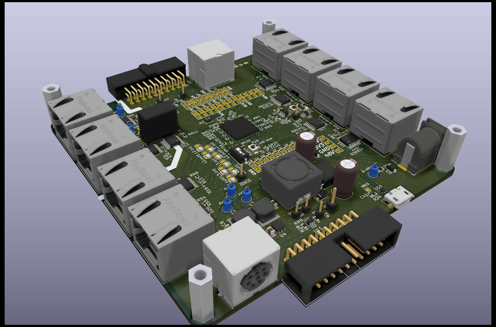
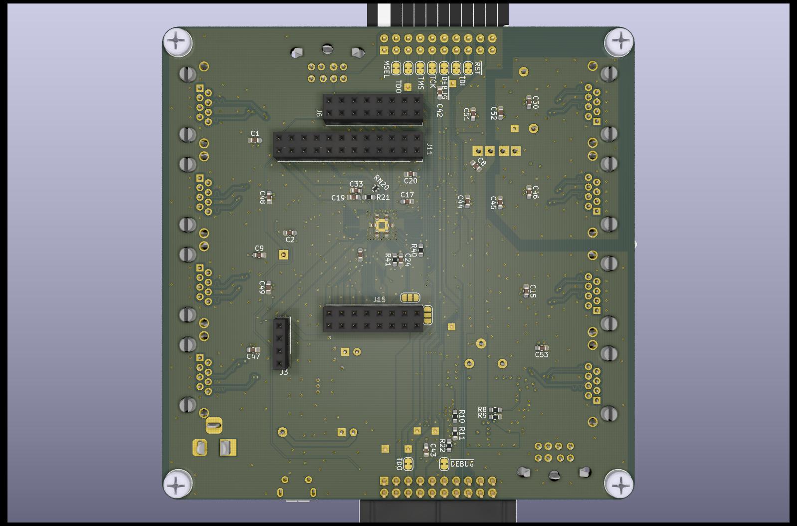
Schematic, board layout and virtual reality files can be found here.
https://github.com/lilltroll77/XMOS-XU216_FB236-BOARD
---------------------------------------------------------------------------
Here is an old video when using the eXplorer KIT + stepper motors + the machine itself.
https://www.youtube.com/watch?v=MYEp6bmtVj4
https://www.youtube.com/watch?v=U8llYMeUdWE
https://www.youtube.com/watch?v=jBj-VGELGH0
First BLDC version can be found here with eXplorer KIT.
https://workspace.circuitmaker.com/Proj ... put-driver
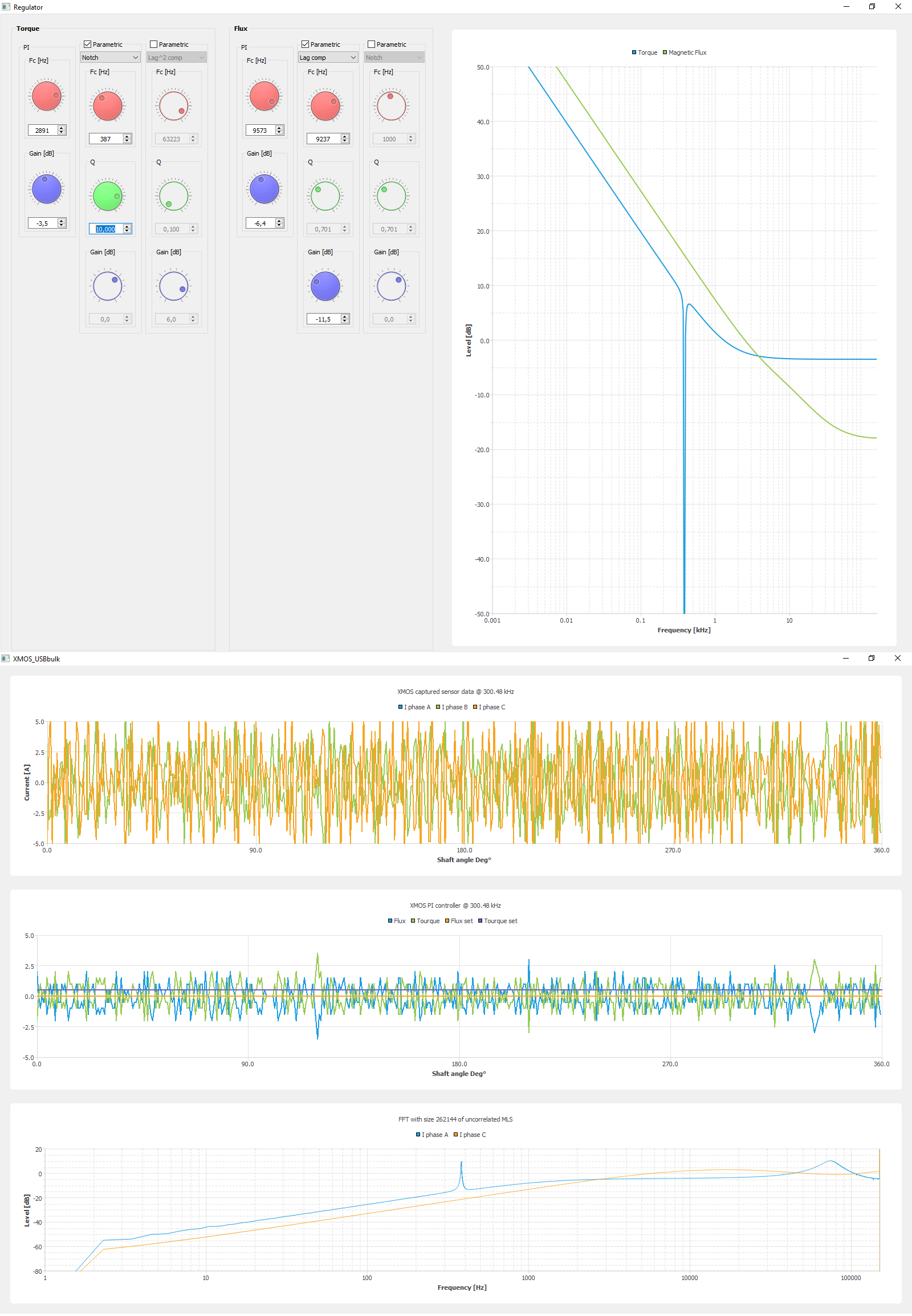
There is also a large GUI on the host side written in Qt (C++). Below is 2 early pictures. XMOS streams ~ 10Mbyte/s of controller real-time data to the host over a custom bulk USB driver.
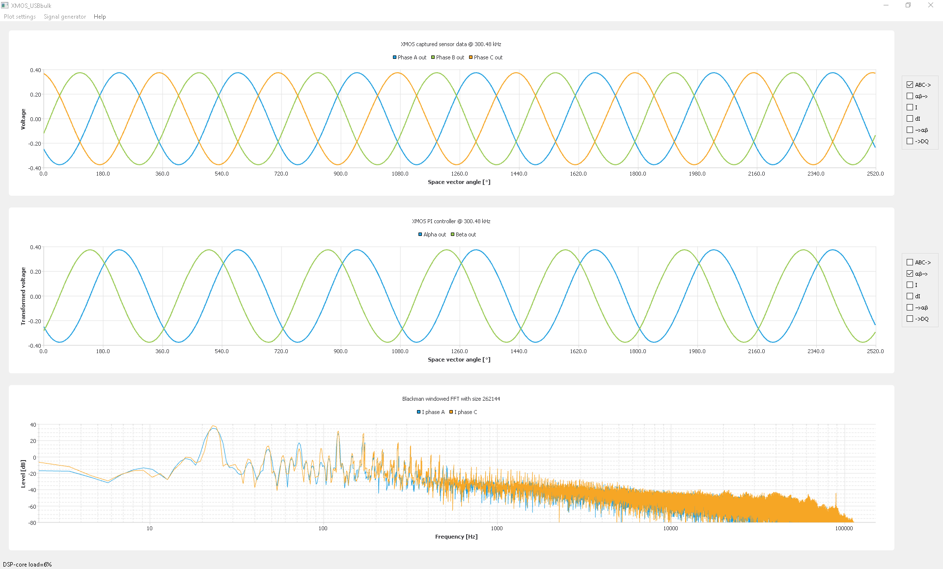
GCODE for moving the robot is created by the http://openpnp.org/ software which also uses machine vision.
Schematic review needed - robotic project.
-
- XCore Expert
- Posts: 956
- Joined: Fri Dec 11, 2009 3:53 am
- Location: Sweden, Eskilstuna
Schematic review needed - robotic project.
Probably not the most confused programmer anymore on the XCORE forum.
-
- XCore Legend
- Posts: 1913
- Joined: Thu Jun 10, 2010 11:43 am
Hi. Wow - nice project and a lot of hard work!!
From a cursory and late night review, a bit concerned about the +3v3, +1v0 rail bring up and their relationship to the #RESET trigger.
Primarily concerned about the INH pin of the ST +1v0 regulator being strapped to the +3v3 rail. The datasheet for the ST regulator is noting that INH needs to be about +1v2 / 1v3 and the regulator will ENABLE. Fearing that the +1v0 rail may be reached sooner than the +3v3 rail settles and more so, the downstream #RESET trigger threshold is reached to release the CPU out of reset prematurely (while +3v3 rail is not yet reached). Yet the #RESET has to be released within the required time of docking of the USB connector in order for the host PC to enumerate to see this USB driven widget.
Also, not understanding how the TPS3808 is working. Which exact p/n will you be applying? Believe this should be the TPS3808G09? If not, how will the resistor voltage dividers work on the SENSE pin to this device? It is late here so may be confused but you have a 10k and a 7k5 for this voltage divider yet mapping to the +1v0 rail? Will this function correctly? Why not apply a 0v9 threshold rated voltage detector and directly connect to the +1v0 rail for this monitoring? Once the 0v9 threshold is reached, #RESET will become high after your delay expires. This delay must be under the USB enumeration time period.
Is D1 LED polarity (Power ON RESET block) and logic correct? The TPS (reports? - bad joke from Office Space) will be LOW for a brief moment of time, the inverter will invert to a logic HIGH and only then LED D1 will be ON; OFF otherwise. Is that the desired effect? Thinking you want LED to be ON once the #RESET line is HIGH?
(side off topic) Reference:
https://www.youtube.com/watch?v=jsLUidiYm0w
* actually met the lead actor at an airport with his gf (we were all on the same plane) but he over heard us recognizing him from Office Space and he ran to his next gate as though we were paparazzi
C10 will be a high enough voltage rated cap to accept the +48v (or higher) Vin?
Is the +5v0 @ 500mA (max) enough current to power this complete design?
Where does +3v3ISO get used? Could not locate the isolated power supply rail label in the posted schematic.
An alternate option to using the Silabs digital isolators (which we have used in high volumes) is the relatively new TI devices which include an INTERNAL isolated DC-DC power supply along with the isolators inside a single package. Neat part that works well and saves on PCB space. May also offer a higher level of isolation to the design but be sure to carve out the PCB to support the isolated barrier.